


Summary
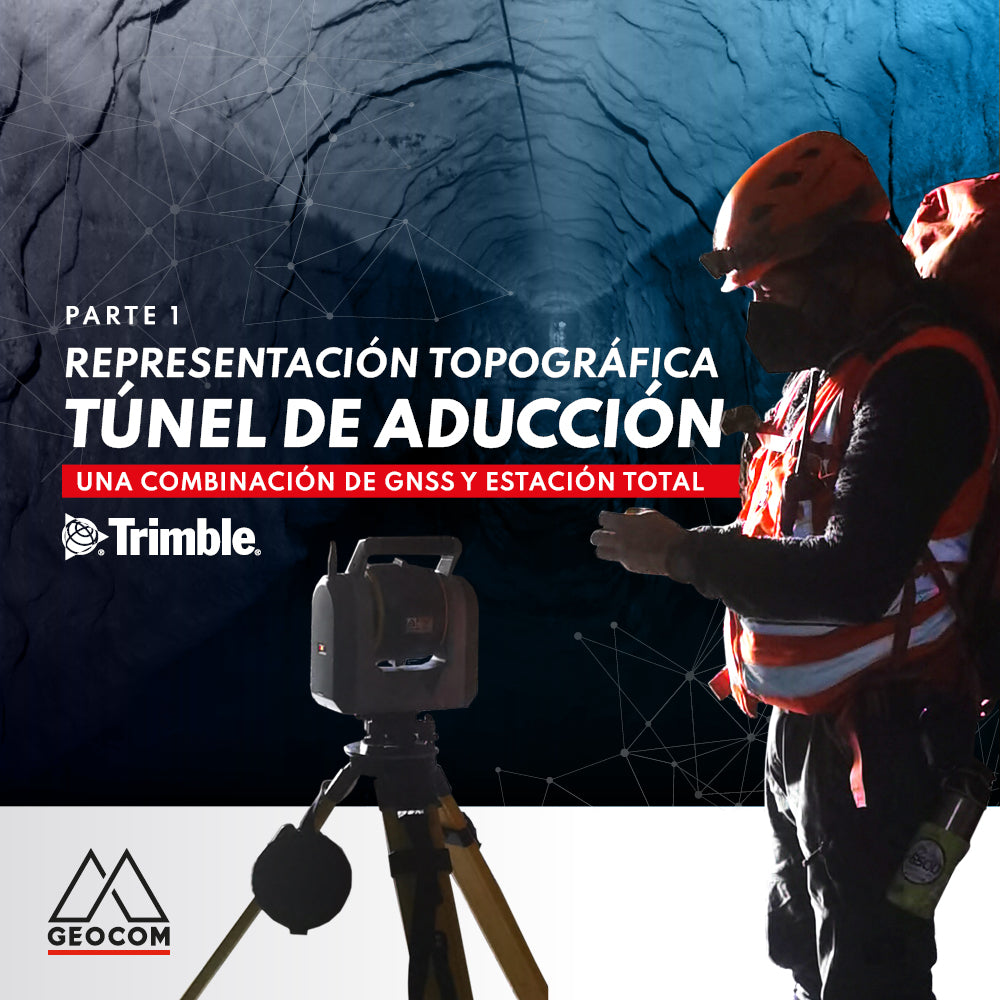
We had the opportunity to work with Rumbos Geomensura on a detailed topographic representation of a more than 7 km long adduction tunnel. The main challenge of this task was the geodetic control required by a laser scanner to ensure that the scans do not lose orientation through the progressive recording of the stations. For this reason, it was decided to carry out a traverse with stations every 200 m, trying to densify positions using points identifiable in the scans. In addition, the terrestrial observations produced by the total station were combined with satellite observations to properly reference this determination.
Reference Frame
First of all, it must be noted that there is no origin or other type of previous geodetic evidence to reference the coordinate determination. For this reason, it is concluded that a combination of GNSS and total station observations is necessary. Considering this, the origin of the network will be given by the EILA station belonging to the GEOCOM GNSS Network, which has a coordinate adjustment based on SIRGAS 2021.00. Regarding the coordinate system, it was decided to calculate a customized Transverse Mercator projection for the horizontal representation, while the vertical component will be established based on the transformation of ellipsoidal heights into orthometric heights using the EGM08 geoid model.

Fig 1. Parameters of the customized Transverse Mercator projection with SIRGAS 2021.00 reference
Starting Field Operations
The work team consisted of 4 people. At the beginning of the field operation, the team split into 2 groups of 2 people each. The first group identified two breaks in the tunnel's alignment, which further complicated the work. This group took the Trimble SX12 scanning total station to the first traverse position. This position was a kind of portal where water flows out to be redirected to the surface. Thus, it was decided to perform a free station from points determined with GNSS in RTK. Three GNSS RTK baselines were observed, materializing the first points with centimetric precision. While it was not the best in terms of accuracy, it was the fastest and most agile approach that could be developed. For this purpose, the robotic feature of the Trimble SX12 was vital, as it required mobility with GNSS and the prism outside the position where the total station was installed.

Fig 2. Initial control points observed with GNSS and then with a total station
GNSS RTK observations at the beginning of the geodetic structure
For GNSS RTK observation, we used a Marksman base that allows positioning a GNSS antenna or a prism without the need to mount a bipod or tripod. Undoubtedly, this base was of great help throughout the entire geodetic observation work, simplifying transfers.
Regarding GNSS observation, an RTK observed control point was established. This means that the position was occupied for 180 seconds. It is important to note that baselines of more than 29 km were observed in RTK mode through the NTRIP link established by the GEOCOM GNSS Network. This operation made a difference in productivity compared to a static observation, which requires more time to converge to a centimetric precision solution.

Fig 3. Details of the RTK baselines observed at the beginning of the network
Geodetic Network Realization
For monumentation, Hilti nails were used for the total station positions, which would, of course, later be occupied by a prism. This methodology was important to ensure the unambiguous positioning and orientation of the instruments, as well as for them to be used as identifiable points for scanning (after placing a target on the point).

Fig 4. First position of the traverse occupied by the 360° prism
Free station as an orientation method for the traverse
Taking all the above into account, a free station could be determined with an orientation error of 11.6” and precisions of 0.2 mm in easting, 1.2 mm in northing, and 0.3 mm in elevation, which speaks very well of both observations made. The analysis indicates that there is no great deformation of the geometries produced by GNSS compared to the total station, achieving a sufficiently precise orientation determination for the geometric conditions offered by the space.

Fig 5. Details of the free station
Precise observation with the total station
At the end of the free station, the densification through the traverse began. For the productivity reasons already mentioned, it was decided to only make one observation per point on both faces of the instrument with the automatic aiming system activated. For these purposes, the Trimble SX12 features Autolock, achieving precise locking onto the prism and avoiding visual observation by an operator. Usually, in this operation, high redundancy is sought by observing 4 or 5 cycles; however, the productivity criterion had more weight on this occasion, so precision and degrees of freedom were sacrificed for faster progress. In this sense, the achieved productivity was as follows:
| Day | Number of total station positions / time | Number of GNSS positions / time |
| 1 |
15 |
3 |
| 2 |
21 |
0 |
| 3 |
6 |
2 |
Table 1. Productivity obtained

Fig 6. Trimble SX12 in operation
In total, 42 total station positions are established, additionally densifying 50 positions to georeference the scans. Regarding the traverse observations themselves, the following statistics are summarized:
- 4.23” root mean square error in horizontal angle residuals.
- 5.65” root mean square error in zenith angle residuals.
- Less than 1 mm root mean square error for inclined distances.

Table 2. Summary of angle and distance observation for a station
GNSS RTK observations at the end of the geodetic structure
Finally, to achieve control at the closure of the geodetic structure, 2 points were measured with GNSS RTK. The peculiarity of this observation was that the coordinates of these points were determined inside the tunnel itself, but taking advantage of a certain opening that existed in what is called a "false tunnel". Unlike the beginning, the same GNSS setup was used to install a 360° prism and perform the observation with a total station.

Fig 6. Details of the RTK baselines observed at the end of the network


Fig 7. Final control points observed with GNSS and then with a total station
Geodetic network adjustment
With all this data, a least squares adjustment is performed by directly combining the GNSS observations with those made using a total station. This approach definitely provided the necessary robustness to the network so that the solution was representative in probabilistic terms.
Regarding the initial and final geometries, the following applies:


Fig 8. Combination geometries for GNSS and total station
With 81 degrees of freedom, the adjustment is performed, obtaining average precisions of 16 cm in easting, 16 cm in northing, and 10 cm in height.

Fig 9. Adjustment of the geodetic network

Fig 10. Complete geodetic network integrated by satellite and terrestrial observations
Conclusions
The combination of GNSS and total station is not merely a whim to be carried out by surveying and geomatics professionals; it is a possibility that offers robustness when adjusting observations.
The geometry of a tunnel clearly conditions the design matrix of a geodetic network; however, this can be solved through the combination of observations.
Regarding the development of the traverse itself based on terrestrial observations, it can be stated that it is a highly complex task. First, it must be ensured that the observation itself is of quality, which is intimately related to the use of automatic aiming systems such as Autolock and Finelock. On the other hand, the conditions presented by a tunnel make this work even more difficult: it is necessary to follow an observation protocol that minimizes the possibility of committing errors in the measurement of instrumental heights or in the identification of targets.

Fig 11. Work Team. Thanks to Rumbos Geomensura.
Compartir:
USBL System | Underwater acoustic positioning
OPINION COLUMN | LiDAR Technology: More Than Just Distance Measurement