

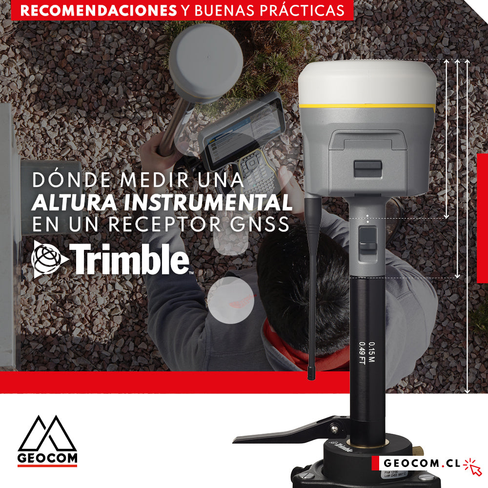

One of the most important procedures during a GNSS observation is the measurement of the instrumental height. This magnitude directly affects the vertical component obtained. Whether for real-time or post-processing positioning, the operator must be careful about its correct determination.
A key aspect for the correct determination of an instrumental height is knowing the physical parameters of a GNSS antenna. As an example, the reference points of a Trimble R12i receiver are presented (Figure 1):

Fig 1. R12 receiver reference points
From Figure 1 we have the following definitions:
- GNSS receiver diagram
- Antenna bracket base
- Quick release base
- Height measured to the antenna phase center
According to Figure 1, the following configuration can be performed in Trimble Access

Fig 2. Configuration of the reference for instrumental height measurement
This configuration considers reduction 3 from Figure 1, therefore, the height to be entered during the survey corresponds to the pole height. In general, for Trimble 2-section poles, this value is 2 m. This configuration is associated with RTK - PPK mobile devices or installations using bipods.
Another important reference in Figure 2 corresponds to the R10 extension lever. This configuration is associated with installations on tripods, for RTK (base) surveying and GNSS networks. Figure 3 presents the explained reference:

Fig 3. Reference 4: R10 extension lever
As mentioned above, this configuration corresponds to an installation on a tripod, therefore, the height measurement must be taken diagonally, in direction 4. Figure 4 presents a standard installation:

Fig 4. Installation of a Trimble R12i receiver on a tripod
Regarding the antenna phase center and antenna bracket base configurations (Figure 2), the following applies:
- Antenna phase center: reduction to the antenna phase center, used in integration procedures, can be configured considering the parameters in Figure 1.
- Antenna bracket base: corresponds to the reference for R-series RTK mobile devices, prior to R10, such as R6, R8, R8s, where a pole is usually used.
The configurations presented are also compatible with the Trimble R10 receiver.
According to Figure 2, the height correction depends on the chosen model (R12i). If we change this model to R8s, the following applies (Figure 5)

Fig 5. Reference height for an R8s receiver
From Figure 5, in addition to "antenna bracket base" (associated with RTK), 2 new reference points are recognized, which are presented in Figure 6

Fig 6. Reference heights on Trimble R8s GNSS receiver
From Figures 5 and 6, the following is defined:
- Center of the protective top: associated with networks, inclined measurement (3)
- Extension lever: common in RTK base installations on forced centering pillars, this lever provides sufficient height to the receiver so that the UHF antenna does not collide with the leveling base, for example.
For DA2 devices in Trimble Access (Figure 7), the following references are recognized:
Fig 7. Reference points for instrumental height measurement for Trimble DA2.
Initially, the "antenna bracket base" reference point is recognized. This reference is presented in Figure 8

Fig 8. Reference point antenna bracket base.
Another reference in Figure 8 is Bottom of pole cap long. This reference involves using the adapter shown in Figure 9

Fig 9. DA2 extender adapter, Bottom of pole cap long
Finally, the reference called "Bottom of Catalyst antenna handle" corresponds to the adapter presented in Figure 10

Fig 10. Adapter for Trimble DA2: Bidirectional line corresponds to the distance to the antenna bracket base, unidirectional arrow refers to the measurement.
For Zephyr 3 Geodetic antennas, we find two reference points (Figure 11)

Fig 11. Reference points for the Zephyr 3 Geodetic antenna.
For this configuration, two measurable configurations are supported: antenna bracket base and notch base. For the first case, the references are the same as in the previous points. For the "Notch base" reference, the antenna is mounted on a tripod. Measure the height to the base of the notch on the side of the antenna (Figure 12).

Fig 12. Zephyr Geodetic "notch base".
For Zephyr 3 and Zephyr 3 Tornado antennas, the references are analogous to Zephyr Geodetic 3. The geometry of these antennas is presented in Figure 13:

Fig 13. Offset between antenna bracket base and notch base for Tornado and Zephyr 3 antenna.
The modification of an instrumental height can be performed from Trimble Access (Figure 14)

Fig 14. Modification of instrumental heights in Trimble Access.
This can also be done from Trimble Business Center when importing a GNSS observation file, Figure 15:

Fig 15. Modification of instrumental heights in Trimble Business Center.
This document presented the instrumental height measurement references for Trimble receivers. This parameter is key for optimized vertical component reduction.
Compartir:
Trimble RTX application under SIRGAS-Chile 2021
LiDAR RIEGL | Railway Bridge Survey