


Summary
Topographic modeling of a tunnel using a laser scanner offers significant advantages in terms of the representativeness and quality of data obtained in the field. However, several challenges arise related to correctly maintaining the orientation of the different scan positions that make up the project due to the geometric defect present in this type of scenario. In this second part of the experience with Rumbos Geomensura, the field survey process carried out with a laser scanner will be shown, in addition to the management of the point cloud to go from isolated scan positions to a registered and correctly georeferenced point cloud to obtain final products that represent the existing geometry.
Field Survey
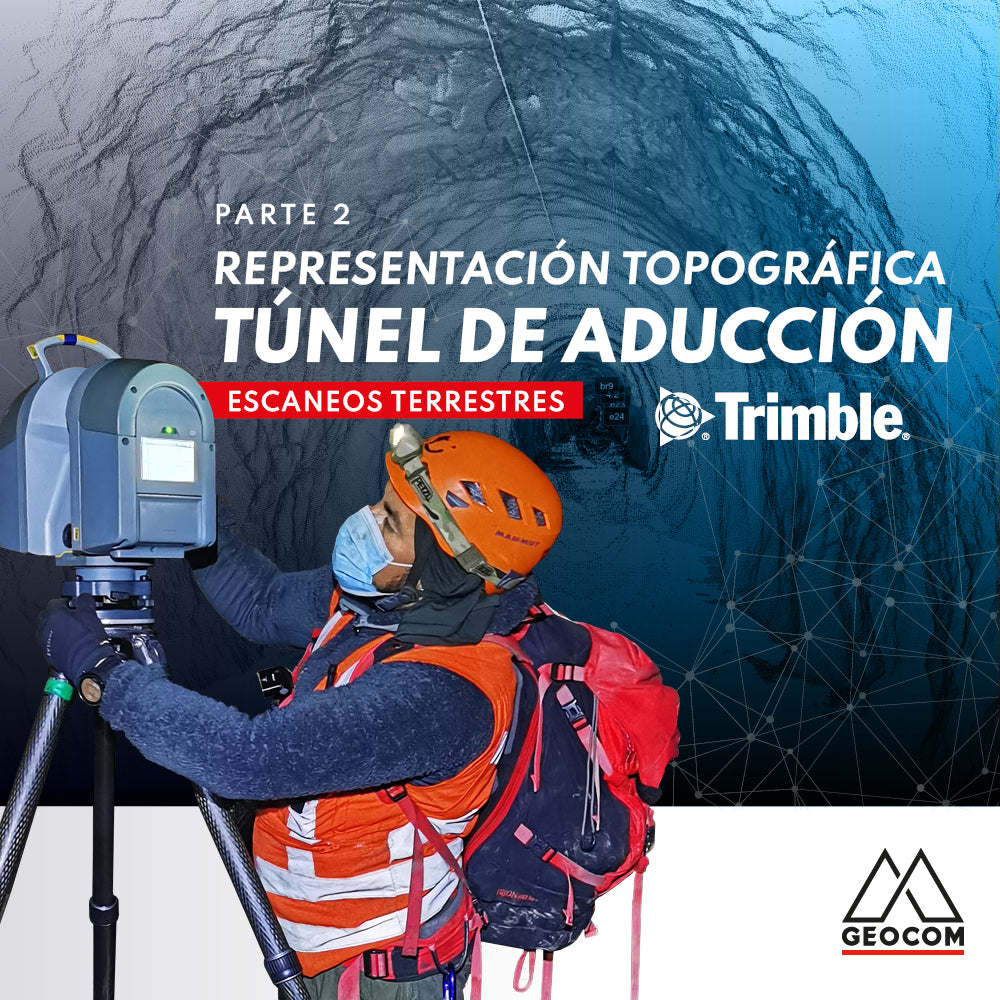
Rumbos Geomensura, a company specializing in topographic representations from laser scans, has a Trimble TX6 laser scanner with which they have participated in a variety of projects. After completing the geodetic structure (on which the scans are framed), shown in the first report of this experience, the intensive scanning tasks begin.
The measurement process using a laser scanner in this type of situation is primarily conditioned by the tunnel's geometry, as the scanning range is not very extensive. In this regard, to achieve appropriate density in the tunnel's representation, it was necessary to perform stations at distances no greater than 25 m (depending on the scale of the tunnel section).
Thus, the Trimble TX6 laser scanner was progressively stationed, maintaining this equidistance. Additionally, strict leveling of the instrument was maintained, keeping the compensator active. This will be of great help when registering the scans, as the instrument will remain vertical using its natural orientation. To establish a reference between the different stations, a pair of cones were installed, creating a link between consecutive positions, which will aid in generating the scan registration. Additionally, at specific locations where the polygonal stations are located, black/white targets were placed to allow for point creation for georeferencing.
This process extended for almost 4 days, during which 282 scan positions were developed.

Fig 1. Field measurement process
Registration
Once the field process is complete, 4 projects are obtained, which are processed using Trimble RealWorks software to perform scan registration.
The process of registering the different scan positions is carried out using the cloud-based registration mode, which uses a common portion of the point cloud between consecutive scan positions to calculate the registration*. For this, when performing the scans, a recognizable object (consecutive cones) was integrated into the point cloud, facilitating the office work and ensuring the correct registration of each scan position along the tunnel, and simplifying this procedure.
* Reference registration modes https://www.geocom.cl/blogs/news/nube-de-puntos-registro-referenciacion-y-georreferenciacion
The registration process is performed between consecutive positions, maintaining previously adjusted positions as a reference to register the entire path. However, this process cannot be carried out indiscriminately: without control, the cloud may tend to show deformations in terms of what is known as drift. This effect is independent of the method used to register the clouds, whether using objects or cloud-based registration, being an inherent condition of the geometry of the scenario to be represented. In less demanding representation situations, drift is controlled through a large overlap between clouds, a situation that does not occur in a tunnel.

Fig 2. Cloud-based registration / visual inspection of registration
Finally, from the scan-based registration report, a real overview of the established precisions in this process and the behavior of the registration in the corresponding day's dataset can be obtained.

Fig 3. Scan registration report
Georeferencing
The georeferencing process is critical in this workflow to provide the reference that has already been established in the traverse. We have already commented on the drift - orientation error - that occurs in the registration itself, which can be increased as the distance from the reference station increases, which would be reflected in an inconsistency between the traverse and the adjustment of the topographic representation from the laser scanner, potentially leading to significant errors as this process progresses.
To solve this problem, it is necessary to georeference in sections not exceeding 300 m of progress, in order to minimize drift in sections that are not yet connected, maintaining the initial geometry. In this way, the drift that may be generated in the registration product of the limited geometry of the tunnel is controlled.
To georeference the produced point cloud, points with known coordinates are available along the entire tunnel route, such as targets on the tunnel floor at defined distances (the same traverse points along with a black/white target) and positions at recognizable points in the point cloud (bireflex, mileage plates, cable conduits).

Fig 4. Example of observed control points
Based on these control points, the different sections that make up the project are georeferenced, maintaining a station with overlapping coordinates throughout the entire route and attempting to keep the georeferencing residuals within acceptable topographic values, ensuring that no double layers are generated in the data overlap areas.

Fig 5. Georeferencing of scans

Fig 6. Rumbos Geomensura
Final Deliverables
The use of Trimble RealWorks was vital for the georeferencing of the point cloud from the progressive registration of scans. In this sense, Trimble RealWorks proposes a highly recommended workflow to be applied to TX series scanners. However, for the creation of the final deliverables, it was decided to use Trimble Business Center through its Tunnels module due to its ease of consolidating this type of report.
The process in Trimble Business Center is very simple, allowing for complete reporting. The first step is to import the point cloud to establish discrete points at a defined interval. These points are associated with a certain PK (length progression along the horizontal alignment) of a tunnel corridor (a three-dimensional alignment along with a design section is required) to be compared in terms of evaluating the excavation.

Fig 7. Discrete points obtained from the point cloud
For these purposes, a circular section is constructed from a three-dimensional alignment that describes the path of the adduction tunnel. One of the first reports that can be obtained to review the representation is a complete report in Word format:

Fig 8. Tunnel report in Word format
This report mainly serves to review the results. In this case, the final deliverable was required in CAD format, exclusively representing the tunnel section. For this reason, the Word report constitutes a useful source for an initial review.
Then, by configuring a tunnel template, various sheets are created, in an established paper format, achieving the desired effect in the required file type:

Fig 9. Final deliverable of the tunnel cross-sections in CAD format
Conclusions
For the correct execution of tunnel projects, it is essential to have a supporting geodetic network that ensures the precision in position and orientation of the tunnel's geometry, so that, from this, the correct georeferencing of the LiDAR survey is assured.
The critical point in this type of survey is related to minimizing the drift of the point cloud. For this, it is important to consider different registration strategies, in addition to georeferencing strategies in the office, with sufficient control points. However, perhaps the crucial part of this process has to do with referencing delimited sections of the point cloud between control points. Clearly, this type of strategy helps to keep the geometries intact, achieving an adequate representation.
Finally, Trimble Business Center is a tool that allows consolidating all the good work done in the field through an adequate presentation of results by means of reports and graphical representations.
Compartir:
Geomonitoring, precision, and automated integration
RTK DIRECT GEOTAGGING IN DRONES