

Integration of Geodetic Observations: Optimizing Geodetic Networks in Tunnels
The development of underground projects poses a significant challenge for Geomatics professionals. From complex geometries for network development to monitoring tasks for detecting displacements in a constantly moving structure, these types of projects become a true test, where technical capability and the incorporation and integration of technologies and accessories are fundamental. In other words, geodetic networks in geometrically complex environments, such as tunnels, require specialized treatment where technological integration is key. This ensures precision in combining various geospatial techniques, always guaranteeing the safety of people and equipment.
If we have to establish a starting point, an underground project is generally linked to a set of control coordinates, which can be materialized using GNSS covering the entire extent of the project (Figure 1). At this stage, the "Datum" of the network, or its linkage to a specific geodetic framework, is defined. Aspects related to network design, as well as processing and least squares adjustment criteria, must be considered. In this case, the project's main network is associated with a series of continuous reference stations linked to various epochs of SIRGAS-Chile, ensuring connection to the National Geodetic Network. Additionally, the great benefit of using continuous GNSS reference stations is the ability to recalculate to obtain a new realization epoch.

Image 1. GNSS Linkage
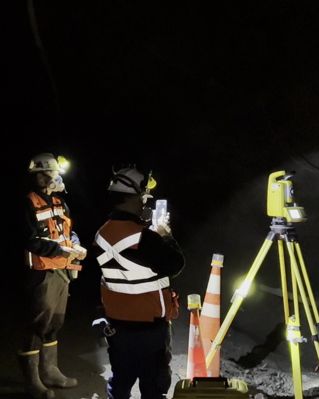
Regarding the underground network, this is approached through terrestrial observations. Here, the challenge of complex geometry (Figure 2) necessitates good planning (pre-analysis) as well as the use of advanced technology throughout the project cycle. At this point, servo-assisted stations for repeated angle and distance observations, which also integrate automatic aiming systems, plus field software that automates the observation process, become key. In this case, Matías Sau, Head of Surveying at Diexa, has full confidence in Trimble technology: “We have been using Trimble S3 for a long time. The total station allows automated observation rounds to prisms thanks to the use of Autolock. This enables us to quickly densify coordinates with the aim of supporting the survey we will develop with a SLAM.”

Image 2. Internal geometry of an underground geodetic network
Regarding accessories (Figure 3), their use provides reliability and productivity at each stage of the project. Through Rothbucher Systeme's proposal, we were able to advance through a series of free stations with the understanding of densifying in pairs: the first two pairs serve for orientation and the second two for densification, says Sau. Finally, this methodology allows for a simplification of the total station setup by having prisms that are installed directly in the tunnel lining, with the main benefit being time savings because only one tripod is needed in the workgroup. On the other hand, the gain in safety is tremendous considering that the work team moves much faster through the tunnel.

Image 3. Rothbucher Accessories
For the integration of terrestrial and satellite observations, it is necessary to have software that allows the efficient and automated combination of observations, enabling the development of underground projects in a global system simply. For this, Trimble Business Center plays a fundamental role in calculations through the combination of GNSS and total station data: a successful case of using the Integrated Surveying methodology.
Case Study: Mining Tunnel
This report analyzes the establishment of a geodetic control structure for an underground project with an approximate length of 3.5 km. As is common in this type of environment, the geometry is complex, making planning and technology crucial for this project. The first stage considers aspects related to observation planning, processing, and adjustment, both for GNSS linkage and for the underground terrestrial network.
In the case of GNSS linkage, active stations in the national geodetic framework SIRGAS Chile 2021.0 (ZAPA, CTPC, ROB1) are available. From these stations, the ALCP and TEBO stations, located at the north and south ends of the tunnel, are calculated. GNSS processing considered IGS products such as precise ephemerides and clock files, along with the Wide Lane processing model, commonly used for long baselines. The average results for the precision of the baselines comprising the linkage are on the millimeter order.

Image 4. SIRGAS-Chile 2021.0 geodetic linkage
Regarding the linkage adjustment, this was carried out using least squares, establishing the active stations as control, ensuring epoch consistency and geodetic framework between them. The results show a reference factor of 0.5, error ellipses with directions of maximum variance defining major semi-axes of 7 mm on average (Figure 5), and an outlier test without rejected observations (Figure 6).

Image 5. Error ellipses for ALCAPARRA, TEBO points

Image 6. Tau-test for outliers - mining tunnel project linkage
For the planning of the tunnel's internal network, a pre-analysis was carried out, considering redundant sequential observations as shown in Figure 6.

Image 7. Simulated geometry in the tunnel
The redundant design aims to obtain better precisions in the final coordinate estimation. Project development under this methodology is key for controlling orientation loss, which is common in longitudinal projects. For the observation process, a Trimble S3 total station was used, performing 4 iterations per point (direct and reverse). The accessories for materializing control points correspond to Rothbucher prisms, which were fixed to the tunnel lining.
Processing and Integration of Geodetic Observations
Initially, the terrestrial network was adjusted without the external control defined by the GNSS linkage. This aimed to validate the proposed design during the pre-analysis stage. In this stage, the proper use of Trimble Access workflows is crucial for automating this analysis, particularly the use of the raw data file in JOB extension.
The obtained results show a post-adjustment with a reference factor of approximately 4, which necessitated an analysis of observations using a Tau-test (Figure 7). After outlier removal, the optimal weights were defined. In a subsequent stage, by calculating the variance-covariance matrix of the adjusted parameters, the average precisions were determined, which reached centimetric levels in the horizontal and vertical components. The error ellipses verify greater uncertainty in the transverse direction of tunnel advance, a common situation in this type of project (Figure 8).

Image 8. Tau-test applied to the terrestrial network without GNSS linkage. Identification of 1 outlier, red box

Image 9. Direction of advance (red line) and orientation of error ellipses (Transverse in semi-major axis)

Image 10. POS63, POS64, CHI1 and CHI2 points, south access to the tunnel

Image 11. Integrated Network
The integration results, particularly for the terrestrial network, maintain the precision levels calculated in previous stages (centimetric), which implies consistency in the framework materialized by the GNSS linkage from the active stations (SIRGAS CHILE 2021.0), which does not modify the quality indicators of the terrestrial network. In this way, the project remains linked to the framework defined by GNSS, maintaining its internal consistency.
Regarding the adoption of a project coordinate system, associated with definitions such as PSAD56. The processing ensures consistency through transformation tools in the GNSS linking stage. For this, the calculation of transformation parameters or incorporation into Trimble Business Center is completely automated. In the case of this project, solutions associated with PSAD56 were also calculated, under the described approach.
CONCLUSIONS
Regarding the main characteristics of this project, important points are considered:
- The linking of GNSS stations near an underground project to an official geodetic framework ensures the consistency of networks observed from these stations, in this case, a terrestrial network in a tunnel.
- The design of a terrestrial network for a tunnel benefits from a design that considers multiple automated observations using robotic stations and appropriate accessories that ensure consistency in the materialization of control points.
- Both the GNSS network or linkage and the terrestrial network must be statistically evaluated separately and together to ensure accuracy, consistency, and reliability. For this, Trimble Business Center's processing and adjustment tools automate the process.
- The final integration is performed in Trimble Business Center, providing results, precisions, and validations in an automated workflow.
- The adoption of a project coordinate system is possible through geodetic transformations or the incorporation of parameters in the GNSS linking stage.
For Matías Sau, "The implementation of the underground topographic network developed by DIEXA plays a fundamental role within the project workflow, as it constitutes the geometric base on which the three-dimensional survey using LiDAR SLAM technology is supported.
The correct materialization of control points, along with their adjustment and validation, allowed the establishment of a reliable and consistent reference system, ensuring the proper georeferencing of the point cloud.
This aspect is critical, as the quality of the three-dimensional survey does not depend solely on the scanner, but on the level of geometric control of the supporting network, thus allowing its use in operational applications such as volume calculations, geological block models, progress control, and mining planning."
We thank Diexa and its Head of Surveying, Matías Sau, for providing the technical data and field experience essential for the preparation of this document.

Compartir:
[GEOCOM WEBINAR] Gaussian Splatting in DJI Terra
[WORKSHOP GEOCOM] Incorporating Trimble RTX into GNSS networks