

INTRODUCTION
Photogrammetry has greatly contributed to data acquisition for topographic representation at various scales. Clearly, UAS (Unmanned Aerial Systems), better known as drones, have been central to strengthening photogrammetry, becoming a widely used technique in topographic representation over the last decade.
Initially, the advantages of photogrammetry were directly associated with productivity, especially in the case of fixed-wing drones. Later, with the specialization of multirotors, photogrammetry became relevant in much more specific areas, achieving highly accurate massive representations. Furthermore, improvements in digital cameras contribute significantly to the popularization of photogrammetry.
However, in terms of georeferencing, photogrammetry has always required ground control points to transform the coordinates of the aerotriangulated block. This is known as indirect georeferencing, a widely applied methodology by various users that connects with conventional surveying techniques.
In this sense, the coordinates of the control points, which must be photo-identifiable, are determined by GNSS or total station. However, there are situations where it is not possible to measure discrete points due to access or safety reasons.
Also, some aerotriangulation blocks require special geometries of control points due to abrupt altimetric changes or geometric defects in flight planning.
In response to the above, photogrammetry has incorporated GNSS+IMU in determining the camera's pose, allowing aerotriangulation to rely directly on these values, considerably reducing the number of control points, and in some cases, completely eliminating them.
CAMERA POSE
Before delving into the direct georeferencing technique, it is necessary to understand the concept of camera pose.
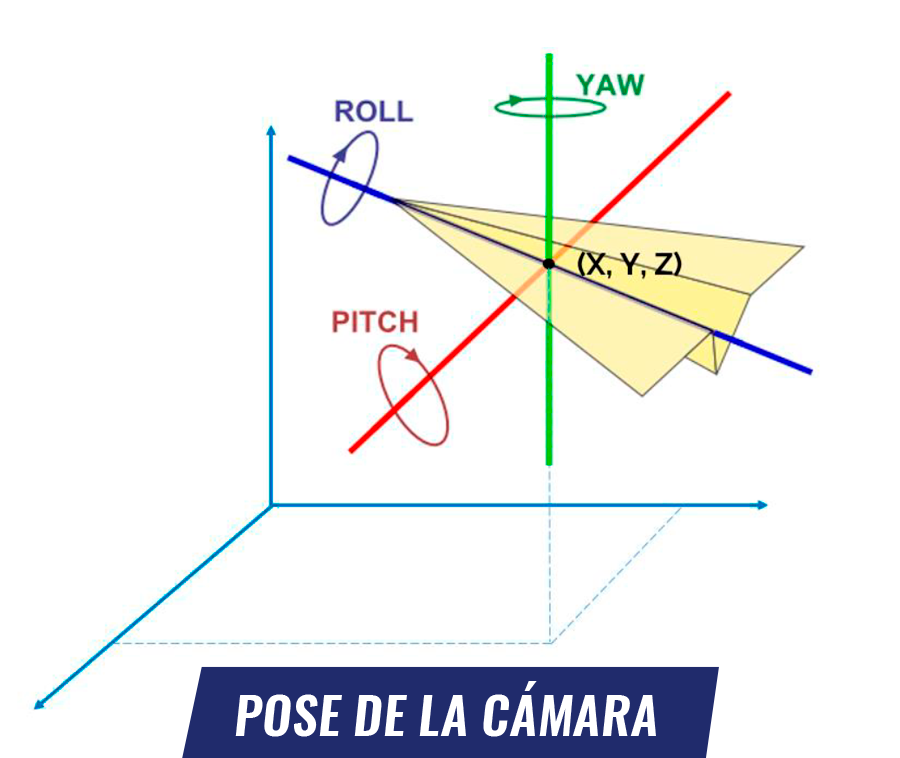
Photogrammetry is directly supported by stereoscopic vision. This means that with a minimum of 2 photographs capturing a common area, it is possible to construct a stereoscopic model that simulates the effect of depth. In other words, photogrammetry allows the change from a two-dimensional projection to a three-dimensional one.
To achieve the stereoscopic model, the photographs must return to the position and orientation at the moment of their capture. This is known as camera pose and is given by 6 parameters: 3 coordinates and 3 orientations arranged in three-dimensional space.
Now, once the camera pose is achieved, which has an arbitrary determination even with a non-true scale, it is necessary to position it in a known reference system. This is where control points are usually used: a coordinate transformation is simply performed using these points.
The variant that uses direct georeferencing consists of determining the camera pose through the processing of GNSS+IMU observations without the need to perform the aforementioned coordinate transformation.
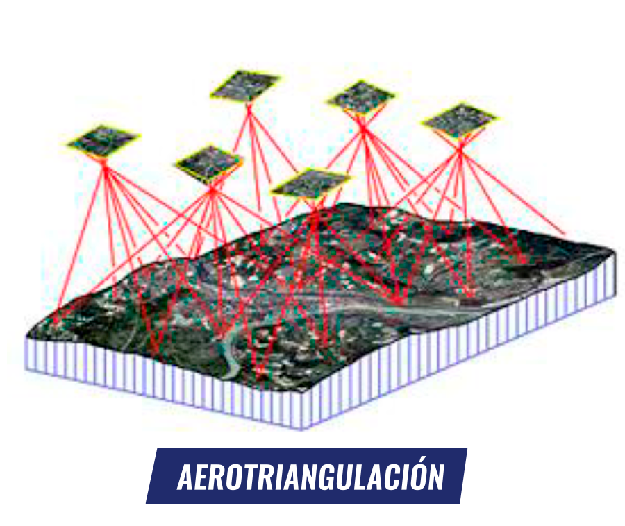
AEROTRIANGULATION
Aerotriangulation is the process of determining the camera pose of the different photographs acquired for a specific block. Aerotriangulation is based on advanced image recognition algorithms that automatically determine a multitude of tie points (the same point in different photographs), allowing a least-squares adjustment of the positions and orientations of the different photographs.
GEOREFERENCING
According to the above, the following types of georeferencing are defined:
● Indirect georeferencing: based on the incorporation of ground control points.
● Direct GNSS georeferencing: based on the determination of the coordinates of the principal points of the photographs while the orientations are obtained from the adjustment performed by the aerotriangulation. Strictly speaking, it is an aerotriangulation with a smaller number of unknowns (only the orientations are unknown).
● Full direct georeferencing: the camera pose is determined absolutely by a GNSS+IMU observation. Aerotriangulation is not necessary in the photogrammetric process.
GNSS: PPK vs RTK
There is a broad discussion today regarding the benefits of both techniques. While PPK requires post-acquisition processing of observations, RTK determines coordinates on-site.
However, the RTK methodology requires an uninterrupted radio link, which can result in some photographs not having precise positions. Even so, the GNSS+IMU technique can only be applied in post-processing.

UAS AND DRONES
Regarding unmanned aerial systems, they are classified into two main types: fixed-wing and rotary-wing. Each of these has its respective advantages and disadvantages, which are important to know so that, depending on the characteristics of the project to be carried out, the most suitable equipment is used.
Fixed-wing
These are similar to conventional aircraft, as they have a known structure, generally equipped with one or two engines. Their advantages are:
● More efficient aerodynamics
● Higher travel speed
● Larger survey area
● Greater autonomy
● Higher productivity

Rotary-wing
Also called multirotors, these are equipment with more than 2 motors. Their advantages are:
● Vertical takeoff and landing
● Ideal for confined spaces
● Visual inspection (video recording)
● Sensor versatility
This document will review the Delair UX11 and WingtraOne fixed-wing systems and the DJI Phantom 4 RTK and Matrice 210 RTK V2 multirotors. All these systems feature direct GNSS georeferencing. The Microdrones mdMapper1000DG system, which is equipped with full direct georeferencing (GNSS+IMU), will also be analyzed.
WORKFLOW USED IN DIRECT GEOREFERENCING
Direct georeferencing allows for the autonomous determination of the camera pose. This is done based on GNSS or GNSS+IMU observations. However, the field workflow does not change significantly compared to indirect georeferencing processes.
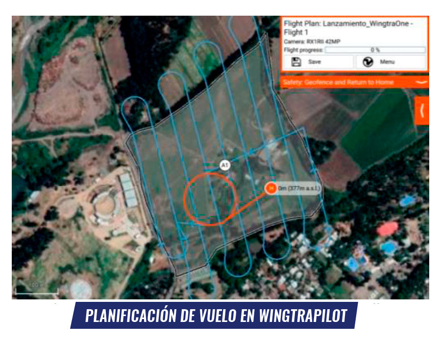
First, flight planning is required, where the layout of the area to be surveyed is defined along with the determination of the flight height – which determines the size of the pixel projected onto the ground – as well as the longitudinal and transverse overlap of the photographs and the direction of the flight lines (which should preferably be perpendicular to the wind direction). The flight planning software to be used depends directly on the UAS, although they are all very similar and allow for quick and user-friendly planning.
 Since direct georeferencing requires processing GNSS baselines, it is necessary to install a GNSS receiver at a point with known coordinates. The GNSS must store satellite observations with a 1-second recording rate, then proceed to the UAS equipment operation, where a checklist must be followed to ensure safe flight operation.
Direct georeferencing produces the camera pose, either completely or incompletely. This determination depends on the processing of GNSS or GNSS+IMU observations. Additionally, to provide the precise position for each principal point of the photographs, a link must be established between the camera and the GNSS or GNSS+IMU. This is known as position interpolation and is performed based on time or an event marker located in the aircraft's GNSS itself.
Next, this will be explored in more detail, understanding that there are equipment with incomplete direct georeferencing, where only the precise position will be obtained (DJI, Delair, and WingtraOne lines), and equipment with complete direct georeferencing, where not only the position but also the precise orientation will be determined (Microdrones mdMapper1000DG).
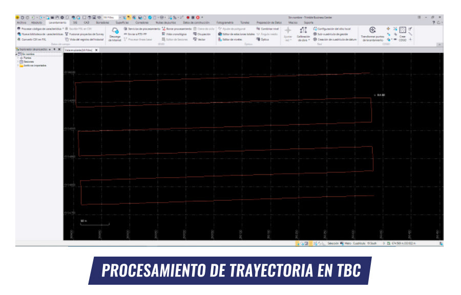
For the DJI Phantom RTK and Matrice 210 RTK V2 products, it is recommended to process the GNSS trajectory with Trimble Business Center software, which allows for determining the coordinates of each GNSS record (flight trajectory).
Once the flight trajectory is obtained, it is necessary to interpolate the exact position of the event. This is why GEOCOM developed the GEOCOM-DJI Application, which associates the precise flight trajectory obtained in TBC with the MRK time file of the events captured by the multirotor.

In the case of Delair UX11 and WingtraOne fixed-wing UAS, Delair After Flight and WingtraHub software, respectively, are used to obtain the precise coordinates of the photographs. Both software differ in their interface and some details and utilities, but they both do the same: process the precise trajectory followed by the aircraft.
The workflow consists of, first, importing the GNSS base data and indicating its coordinates; then importing the data stored in the aircraft (GNSS file and photographs); subsequently initiating the processing of GNSS baselines; and finally obtaining the geotagging of the photographs, which is accompanied by a report on the quality of the PPK processing and the accuracies obtained.
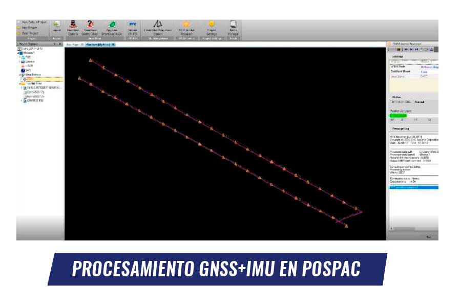
With Microdrones mdMapper1000DG, the complete camera pose (GNSS+IMU) will be obtained using Applanix's POSPac UAV. This is powerful processing software for GNSS and inertial data, as well as for the direct georeferencing of photographs obtained from aerial platforms.
Its workflow is very similar to that performed with other direct georeferencing equipment; that is, a project must be created, a coordinate system defined, the base file imported (with a recording rate of 1 second), and the drone file imported, obtaining through post-processing the position (in x,y,z) and orientation (yaw, pitch, and roll), continuously checking the quality of the navigation data.

The ability to obtain the complete camera pose allows for greater versatility and productivity of operation, since, for example, linear flights can be performed (with one or two lines, as will be seen in the practical case presented later).
Finally, after completing the direct georeferencing process on any of the aforementioned UAS equipment, comes the photogrammetric processing in Agisoft Metashape, which is powerful software that allows obtaining the final products of the survey: point cloud and orthophoto.
A point cloud is a set of positions in a three-dimensional coordinate system designed to represent the surface of an object. On the other hand, an orthophoto is an orthorectified image with orthogonal projection that is the product of aligning the multiple captured photographs. Both products have known reference obtained through the direct georeferencing process.
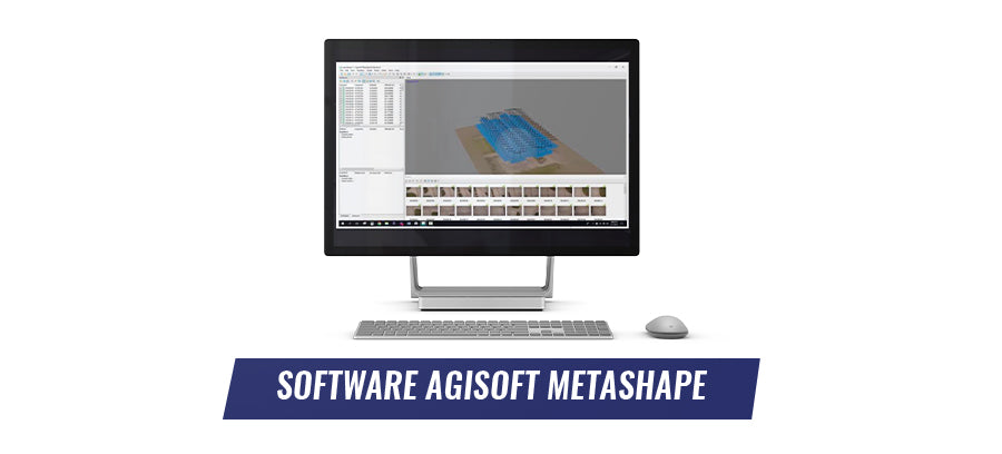
From the point cloud and the orthophoto, countless new products can be generated, such as surfaces, contour lines, volume calculations, etc. The workflow in Agisoft Metashape is as follows:
● Definition of coordinate system
● Import of photographs
● Import of camera pose
● Import of camera calibration
● Photo alignment (aerotriangulation)
● Dense reconstruction (point cloud generation)
● Point cloud classification
● Surface reconstruction
● Orthophoto generation
● Delimitation of the area of interest
● Export to a variety of formats
DJI PHANTOM 4 RTK
This multirotor is a very lightweight and easy-to-operate piece of equipment, with a very intuitive workflow for the user.
The drone is equipped with an integrated 20 MP camera with a 1'' sensor size. Its aerodynamic design allows for wind resistance of 36 km/h, also providing very versatile operation as it is prepared to fly up to 6000 m above mean sea level.
The practical case performed with the Phantom 4 RTK was carried out in a port in northern Chile. The survey aimed to identify the coastline of the coastal area, to then materialize it for port engineering purposes. Some background information on the flights carried out:

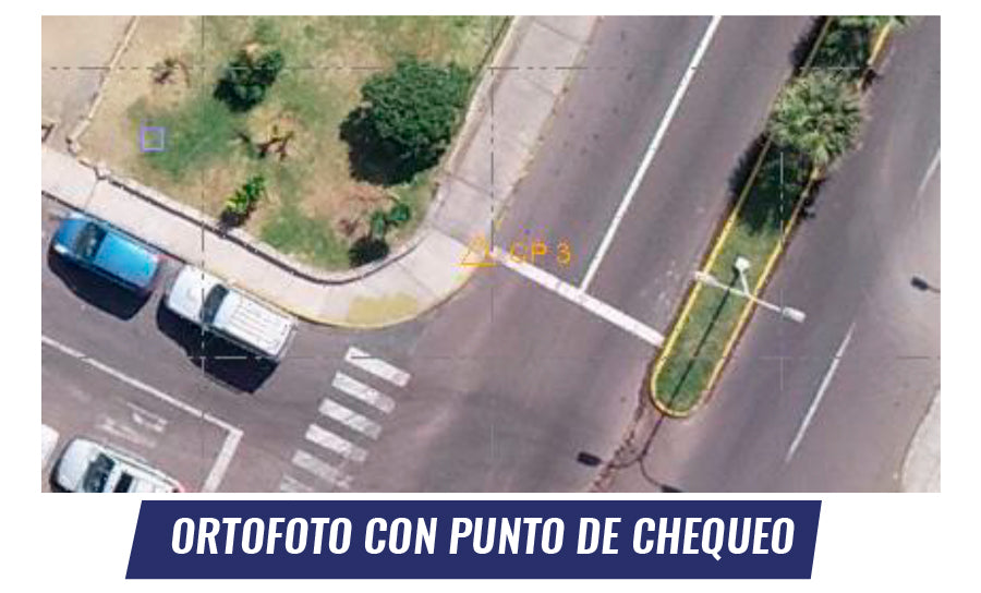
After processing and with the aim of validating the accuracy of the survey, 5 check points (those not involved in aerotriangulation) were measured, installed in easily identifiable areas, such as road and sidewalk vertices.
Below are the differences found in the horizontal and vertical components:

In photogrammetry, the error is directly associated with the flight height, achieving a certain photographic resolution; that is, at a lower height, greater precision is expected than if flights are carried out at higher altitudes (with the same photographic sensor resolution). In the horizontal component, the error is expected to be 1-2 pixels, while 2-3 pixels for the vertical component. In this survey, as the average resolution was 5 cm, the average error is acceptable for the survey objective.

The photogrammetric processing, carried out in Agisoft Metashape, allowed for obtaining a high-resolution orthophoto for coastal identification, as well as a textured three-dimensional surface to determine the height of each element.
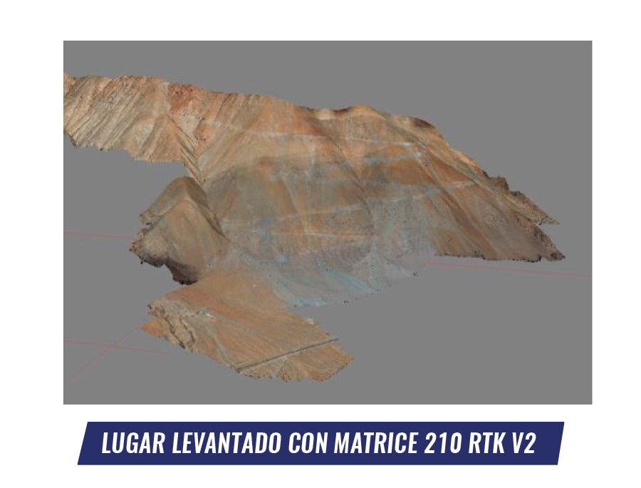
DJI MATRICE 210 RTK V2
The main virtue of the Matrice 210 RTK V2 is its ability to carry a wide variety of sensors (photographic cameras, multispectral sensors, thermal sensors, among others). In addition, it features high-precision GNSS technology that allows for photogrammetric surveys with direct georeferencing, eliminating the need for ground control points. Its aerodynamic design allows for wind resistance of 43 km/h.
The camera used for photogrammetry is the Zenmuse X7, which has an APS-C sensor with 24 MP resolution and a 24 mm focal length.
The practical case was carried out on a hill in northern Chile, where 731 photographs were captured over an area of 400 Ha. The survey aimed to obtain a base topographic representation for the design of a high mountain road.
The practical experience begins by planning and operating 6 staggered flights in order to maintain a constant projected pixel throughout the entire project. This was physically achieved by taking off from 6 different points on the ground with different elevations, due to the project having a 1100-meter elevation change. A table with the main project parameters is shown below:

In this experience, a Trimble R10 GNSS base is used, installed at a point with known coordinates. Regarding flight operations, take-offs were made from 6 different points to ensure the productivity and accuracy of the photogrammetric products.
The post-processed kinematic processing of the flight trajectory, performed in Trimble Business Center, considered the following parameters:


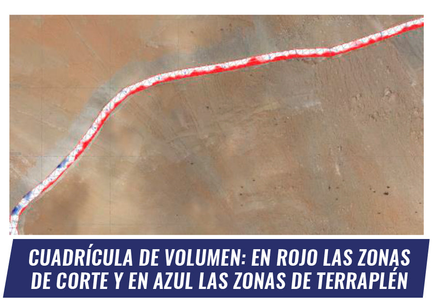
Based on the photogrammetric products obtained in Agisoft Metashape, a corridor was designed in Trimble Business Center and an earthwork report was generated.
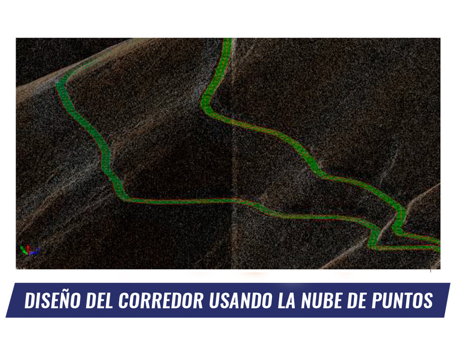
A corridor with a standard template of 6 meters wide was designed to estimate the earthwork generated to widen the existing road.
DELAIR UX11
The Delair UX11 fixed-wing offers an advanced photogrammetry solution. Its aerodynamic design allows it to fly for 59 minutes and cover large areas, resisting winds up to 45 km/h.
The Delair UX11 can take off up to 5000 m above mean sea level, making it ideal for high-altitude work. In addition, its 21.4 MP camera and 12 mm lens feature a global shutter, which eliminates optical distortions caused by aircraft movement.
The practical case was carried out on a railway line where 400 photographs were acquired over an area of 45 Ha. The survey aimed to generate an orthophoto with a high level of detail for railway engineering purposes.

|
Area |
45 Ha |
|
Flights |
1 |
|
Flight altitude |
210 m |
|
GSD |
3 cm |
|
Number of photographs |
400 |
Delair UX11 is a fixed-wing BTOL type, which stands for Birdlike Takeoff and Landing, meaning it takes off and lands like a bird. Takeoff is simply done by launching it manually by the operator, while landing requires a small space.

The flight path processing was performed using Delair After Flight software, and then the photogrammetric processing was done in Agisoft Metashape.


The generated orthophoto will allow for updating the planimetry of the railway line. This digitization is performed in Trimble Business Center, utilizing its advanced CAD drawing functionalities.
WINGTRAONE
WingtraOne is a fixed-wing drone developed in Switzerland, specifically a VTOL (Vertical Takeoff and Landing) type. WingtraOne possesses all the qualities of a fixed-wing aircraft but takes off and lands vertically, which eliminates fuselage wear. This twin-engine aircraft has an autonomy of 55 minutes and weighs 3.7 kilograms. Another great advantage of this system is its powerful 42 MP camera with a full-frame sensor, allowing it to fly at higher altitudes without sacrificing accuracy.
The practical case carried out with the WingtraOne was performed in Peñaflor. The survey aimed to map a road.
For this, the flight planning software, WingtraPilot, allows for planning corridors (linear flight), which greatly facilitates the work, as it allows for rapid and efficient coverage of long and narrow sections with the SONY RX1RII camera.
Some interesting applications in corridor design:
- Road construction, inspection or maintenance
- Railway monitoring and inspection
- Pipeline and power line inspection
- Environmental research, e.g., river mapping

Productivity is the differentiating element in WingtraOne: in a single flight, 6 to 8 km (BVLOS, beyond visual line of sight) and 2 to 3 km (VLOS, visual line of sight) can be covered.
Some flight background information:
|
Area |
20 Ha |
|
Flights |
1 |
|
Flight altitude |
150 m |
|
GSD |
1.9 cm |
|
Number of photographs |
50 |
Photogrammetric survey parameters for a road
The flight operation begins by defining the GNSS base. In this case, it was linked to the GEOCOM GNSS network.
Once the flight is completed, WingtraHub allows for the processing of the flight trajectory, obtaining the precise positions of the photographs in CSV format or geotagging the photos.
Photogrammetric processing was performed with Agisoft Metashape. With these products, further work was done using Trimble Business Center, where the road was drawn based on its CAD tools. This allowed for the generation of a corridor.


The final product generated is a topographic map, which will provide relevant information through cross-sections and longitudinal profiles of the survey:

MDMAPPER1000DG
The mdMapper1000DG system is a powerful and robust multi-rotor drone from the German company Microdrones. It has an autonomy of 40 minutes, withstands winds up to 43 km/h, and can operate up to 4,500 m above sea level. It is made of carbon and comes equipped with a 42 MP Sony RX1RII camera with a full-frame sensor.
This is equipment with full direct georeferencing, where the camera's pose is determined absolutely by a GNSS+IMU observation (position + orientation). This means that the surveyed block is not sensitive to the survey geometry (or at least not as much), since aerotriangulation is not necessary in the photogrammetric process. This makes the mdMapper1000DG the ideal equipment for performing a linear trajectory with only two flight lines, which is very complex to achieve with equipment with direct GNSS georeferencing (where 4 flight lines are recommended for accurate results).
The built-in IMU is an Applanix APX-15, developed by Trimble, and is an integrated board containing both a high-precision GNSS and an IMU (Inertial Measurement Unit).

The optimal application of this equipment focuses on linear and infrastructure projects, which are very difficult to carry out with other equipment due to flight planning.
The practical case that will be shown with this system was a photogrammetric survey carried out on the wall of the Talabre Dam of Codelco, which is located at a geographical altitude of 2470 m above mean sea level.

|
Corridor length |
4 km |
|
Area |
86 Ha |
|
Flight altitude |
120 m |
|
GSD |
2 cm |
|
Number of photographs |
478 |
Photogrammetric survey parameters of the dam wall
Once the photogrammetric survey was completed, the flight trajectory was processed using POSPac UAV software. The result of this process is the complete camera pose through a process linked to the event marker of the inertial sensor; the camera transmits an event to the inertial sensor when triggered, which knows it through GPS time.
Once the precise coordinates and orientations were obtained, the photogrammetric processing was carried out in Agisoft Metashape. The only difference in this process concerns the direct incorporation of the camera's pose. Aerotriangulation is no longer necessary because the 6 parameters of the camera's external orientation are known.
.
For this flight, 5 checkpoints were measured, which served to validate the survey. Below are the results of the measured checkpoints:
|
ID |
Hor. Diff. (m) |
Ver. Diff. (m) |
|
CP 1 |
0.071 |
0.094 |
|
CP 2 |
0.032 |
0.043 |
|
CP 3 |
0.047 |
0.080 |
|
CP 4 |
0.063 |
0.006 |
|
CP 5 |
0.059 |
0.073 |
|
Average |
0.054 |
0.059 |
Horizontal and vertical error at checkpoints

Direct georeferencing in photogrammetry has introduced a new level of productivity compared to methodologies requiring the use of control points. However, it is a technique that demands specialized skills from those who apply it. Beyond photogrammetry knowledge, proficiency in GNSS baseline processing is required, along with an understanding of inertial sensor operation and their processing.
Being able to do without the use of ground control points significantly optimizes time resources and costs associated with fieldwork. The examples developed in this document and the analysis of their results allow us to conclude that the direct georeferencing technique in photogrammetry is reliable and provides accurate results, but a correct working methodology must always be considered to achieve them.
Developed by | Óscar Moreno, Hernán Álvarez, Cristián Michell, Ariel Silva | UAS and Drones, GEOCOM
Compartir:
Participation in the New Mining and Energy magazine
GEOCOM Headquarters Reopening